
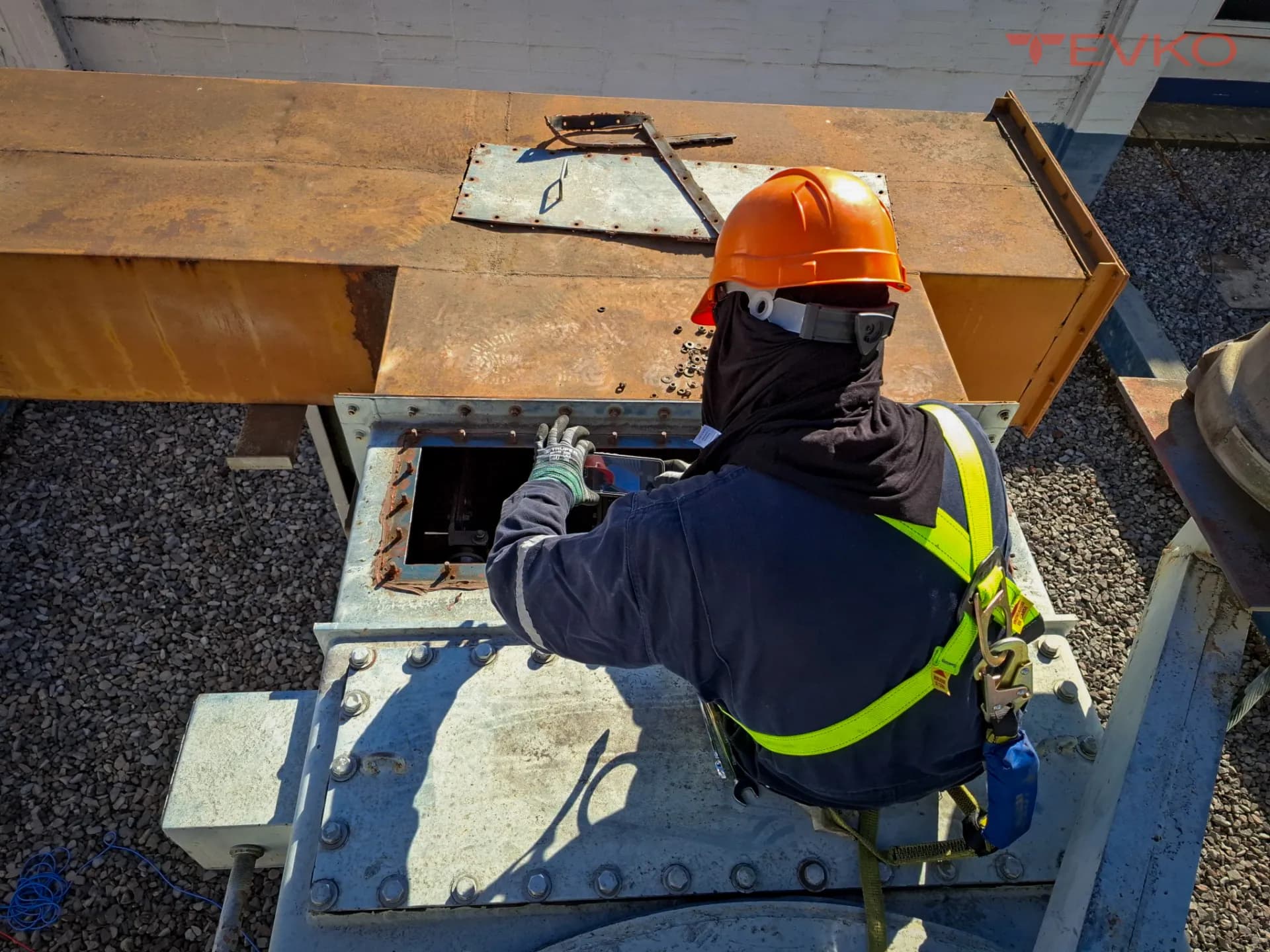
Electrical test
Transformer winding resistance test
Measurement of the DC resistance of windings to detect loose connections, broken strands and bad tap-changer contacts.
The winding resistance test measures the DC resistance of each winding to detect loose or high-resistance connections, broken parallel strands and poor tap-changer contacts. Compared between phases and against history, it separates a connection problem from a winding problem.
The test injects a stable DC current through the winding and measures the voltage drop to obtain its resistance. Because the result depends strongly on temperature, every reading is corrected to a reference temperature (typically 75 °C or 20 °C) before any comparison — an uncorrected resistance value is useless for diagnosis.
Interpretation is by comparison: between the three phases (a deviation beyond roughly 2-3% between phases flags a problem), against the nameplate or factory values, and against the asset's own history. A localized increase points to a loose connection, a broken parallel strand or a degraded tap-changer contact; the test is run at every tap position to map the changer.
At TEVKO we measure winding resistance with Omicron and Megger instrumentation, allowing the inductive circuit to stabilize before reading, correcting for temperature and recording every value in the protocol against phases, nameplate and history — under IEEE C57.12.90 and IEC 60076-1.
What winding resistance diagnoses
High-resistance connection
A localized increase in resistance reveals a loose connection or a broken parallel strand in the winding.
When it applies: After a through-fault, or when localized overheating is suspected.
Tap-changer contact
Abnormal resistance at specific tap positions reveals worn, dirty or open contacts in the OLTC/DETC.
When it applies: Maintenance of transformers with an on-load or de-energized tap changer.
How we run the test
Outage
Transformer de-energized and isolated, windings grounded then released for measurement.
Injection & reading
Stable DC current injected; resistance read once the inductive circuit stabilizes, at all tap positions.
Temperature correction
Every value corrected to the reference temperature before comparison.
Comparison & protocol
Against phases, nameplate and history, with an acceptance verdict in the documented report.
Frequently asked questions — transformer winding resistance test
What does the winding resistance test detect?
Loose or high-resistance connections, broken parallel strands in a winding, and poor tap-changer contacts. A localized increase in resistance, or an excessive deviation between phases, points to where the problem is.
Why must winding resistance be corrected for temperature?
Because conductor resistance changes significantly with temperature. A reading without its temperature and without correction to a reference (typically 75 °C or 20 °C) cannot be compared against the nameplate, the other phases or the asset history, so it has no diagnostic value.
How much deviation between phases is acceptable?
As a guide, a deviation beyond roughly 2-3% between the three phases warrants investigation, though the asset's own history and nameplate values are the definitive reference. It is interpreted alongside the turns ratio and other tests.
Is the transformer measured at every tap position?
Yes. The test is run at each tap-changer position because a degraded or open contact in the changer shows up as an abnormal resistance at specific positions. Testing only the nominal position can hide a changer fault.
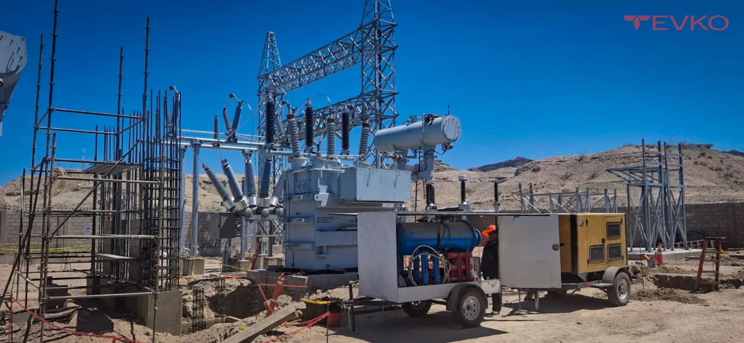
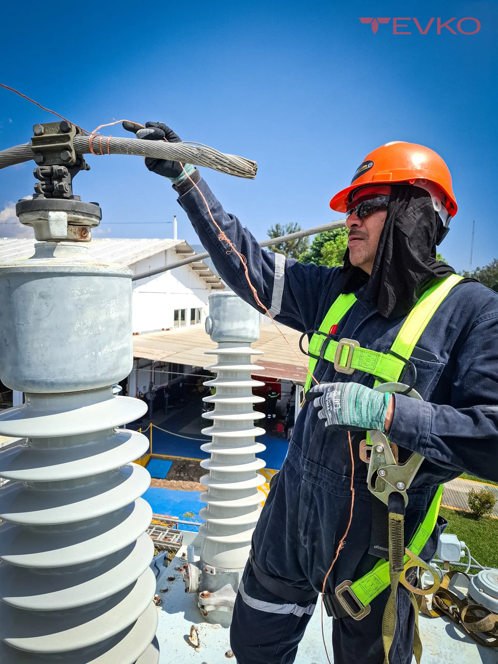
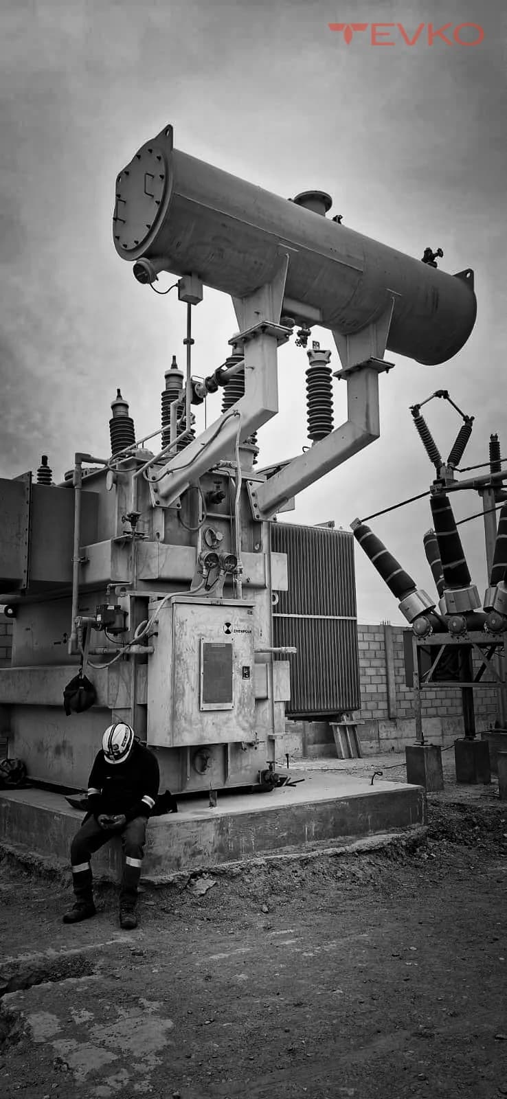
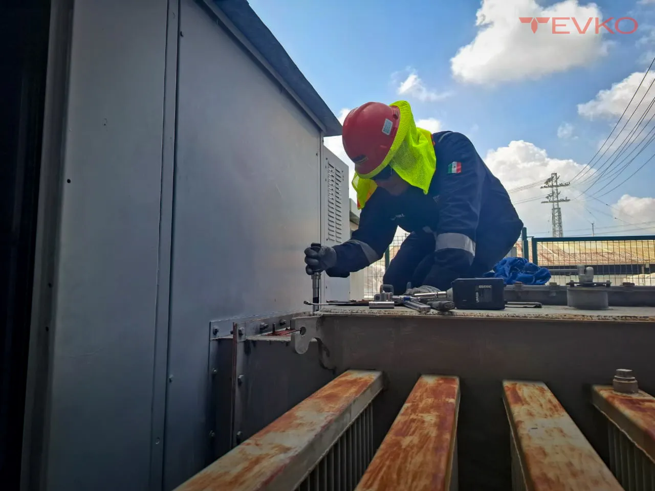
Transformer winding resistance test in images
Related tests and services
Talk to a transformer specialist
Tell us about your asset and we'll respond with a diagnosis and a tailored quote — not generic pricing.