
Electrical test
Ground (earthing) system measurement
Measurement of the resistance and integrity of a substation grounding system to ensure personnel safety and correct protection operation.
The ground system measurement verifies that a substation's earthing has low enough resistance, and intact continuity and bonding, to carry fault current safely. It protects personnel from dangerous step and touch voltages and ensures the protection scheme operates as designed.
A substation's grounding system has two jobs: give fault current a low-impedance path so protections trip, and keep step and touch voltages within safe limits for personnel during a fault. Both depend on a low, stable ground resistance and on the physical integrity of the grid and its connections — which degrade over time through corrosion, loose bonds and soil changes.
The ground grid resistance is measured with the fall-of-potential method (test electrodes at controlled distances), complemented by continuity and bonding checks of equipment to the grid and by soil resistivity when a grid is being assessed or designed. The result is compared against the design value and the limits in the applicable standards; a rising resistance or a broken bond is a safety issue, not just a number.
At TEVKO we measure the grounding system with appropriate instrumentation and interpret it under IEEE 80 and IEEE 81 and the Mexican installation standard NOM-001-SEDE, delivering a documented protocol with the measured resistance, the continuity verification and the recommendations needed to bring the system within safe limits.
What the measurement covers
Ground grid resistance
Fall-of-potential measurement of the grid resistance, compared against design and standard limits.
When it applies: Periodic substation maintenance and after grid modifications.
Continuity & bonding
Verification that equipment is correctly bonded to the grid, finding corroded or loose connections.
When it applies: Safety audits and commissioning of substations.
How we run the measurement
Survey
Review of the grounding design and identification of test points and electrode placement.
Measurement
Ground grid resistance by fall-of-potential, plus continuity and bonding checks (and soil resistivity when required).
Comparison
Against design value and the limits of IEEE 80/81 and NOM-001-SEDE.
Protocol
Documented report with measured values, findings and corrective recommendations.
Frequently asked questions — ground (earthing) system measurement
Why is measuring the substation ground system important?
Because the grounding gives fault current a safe path so protections operate, and it keeps step and touch voltages within safe limits for personnel. A degraded ground system is a direct safety hazard and can prevent protections from clearing a fault.
How is ground grid resistance measured?
Mainly with the fall-of-potential method, placing test electrodes at controlled distances, complemented by continuity and bonding checks and, when assessing or designing a grid, by soil resistivity measurement. Results are compared against design and standard limits.
What standards apply to grounding measurement?
The grounding design and safety criteria follow IEEE 80, the measurement methods follow IEEE 81, and installations in Mexico must comply with NOM-001-SEDE. TEVKO interprets results against these references and the original design value.
Does the substation need to be de-energized?
Ground resistance and continuity measurements are coordinated with the site conditions and safety procedures; many checks are done without a full outage, but the work is always planned around personnel safety and the substation's operating state.
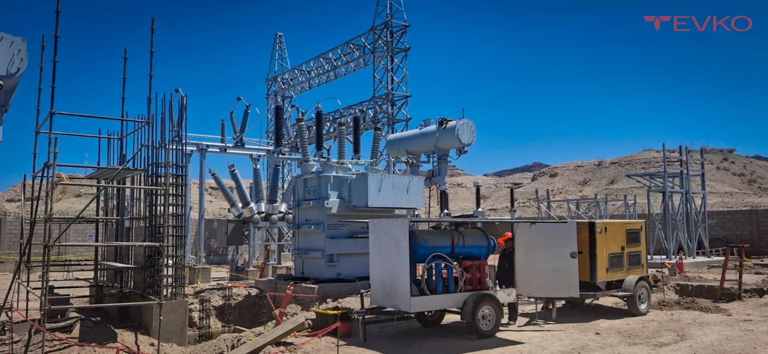
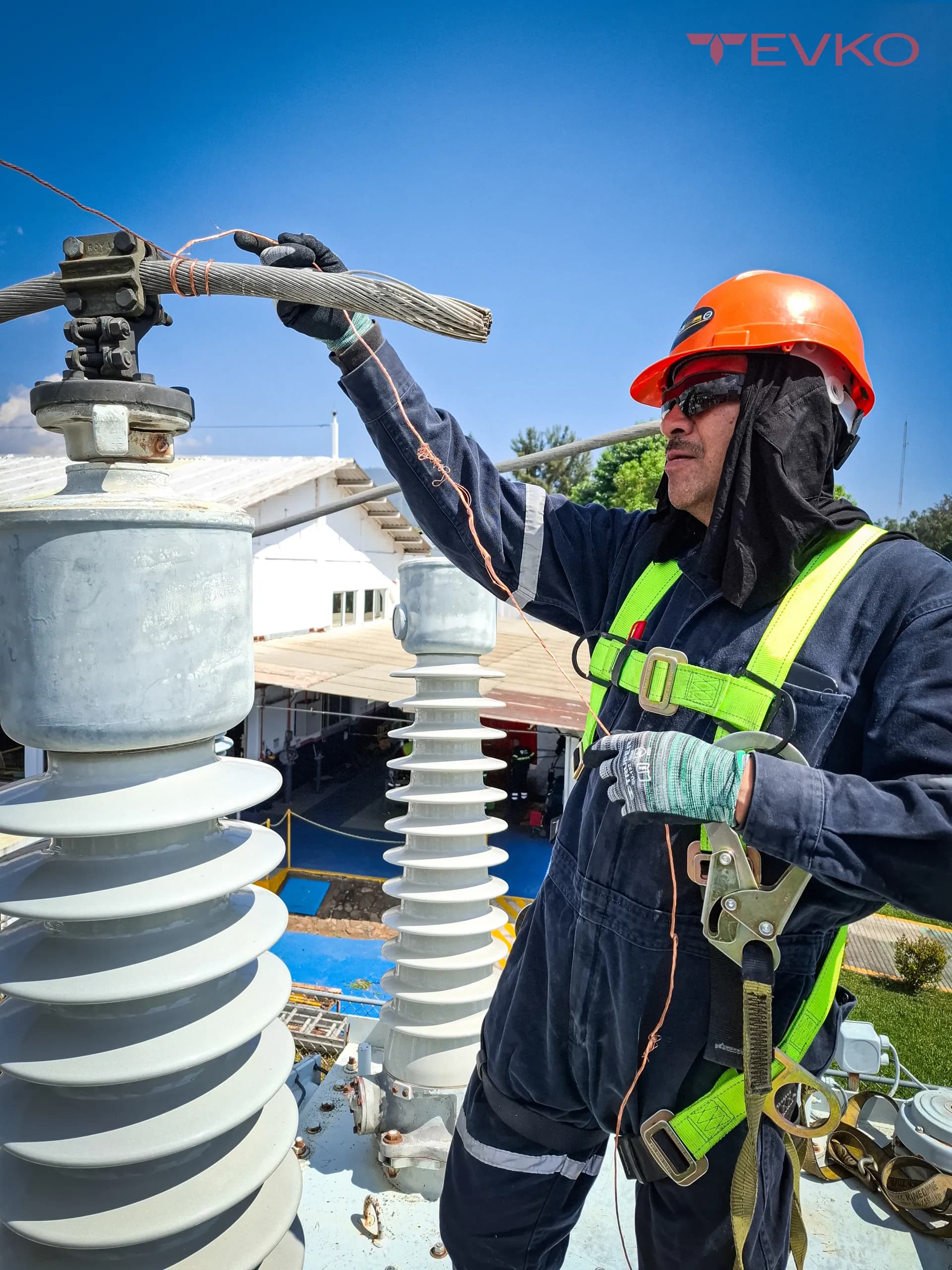
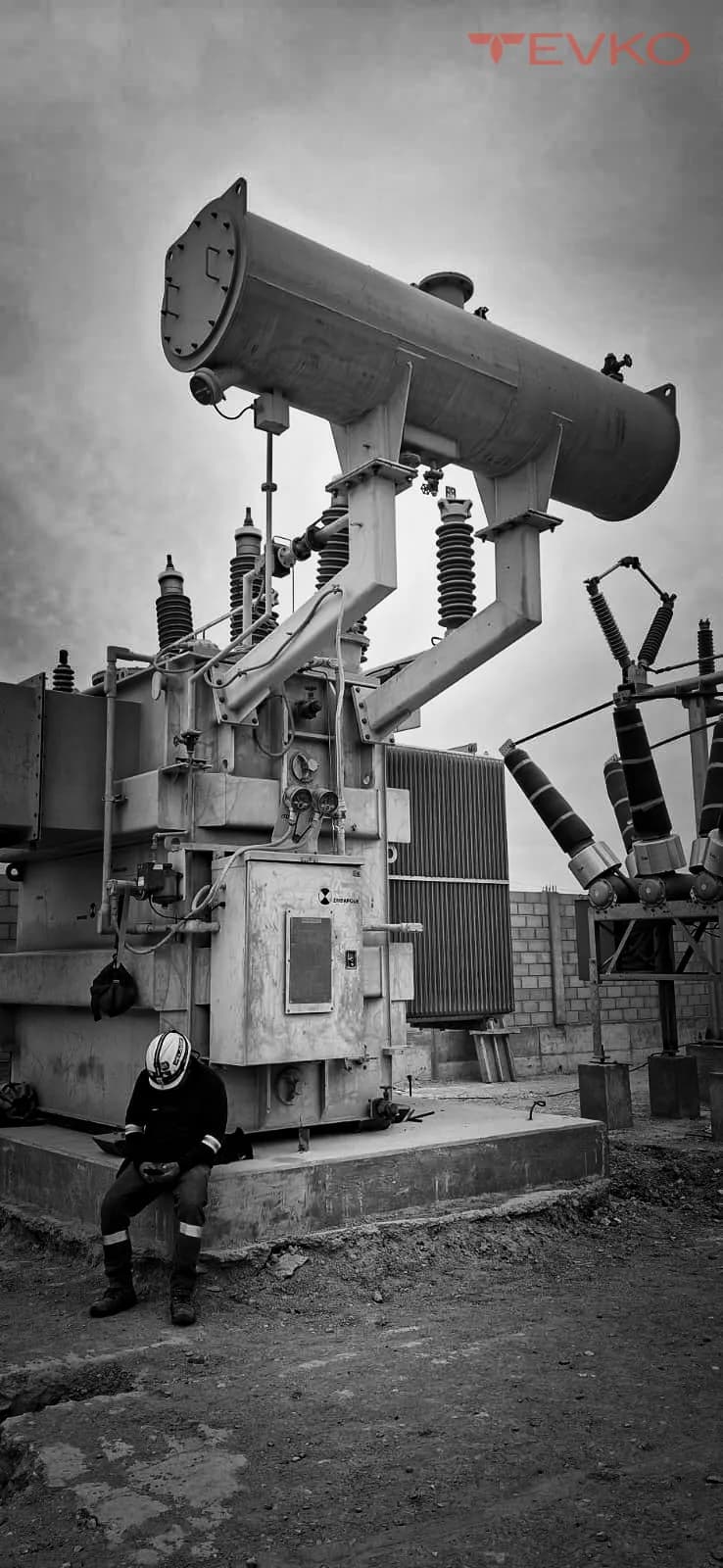
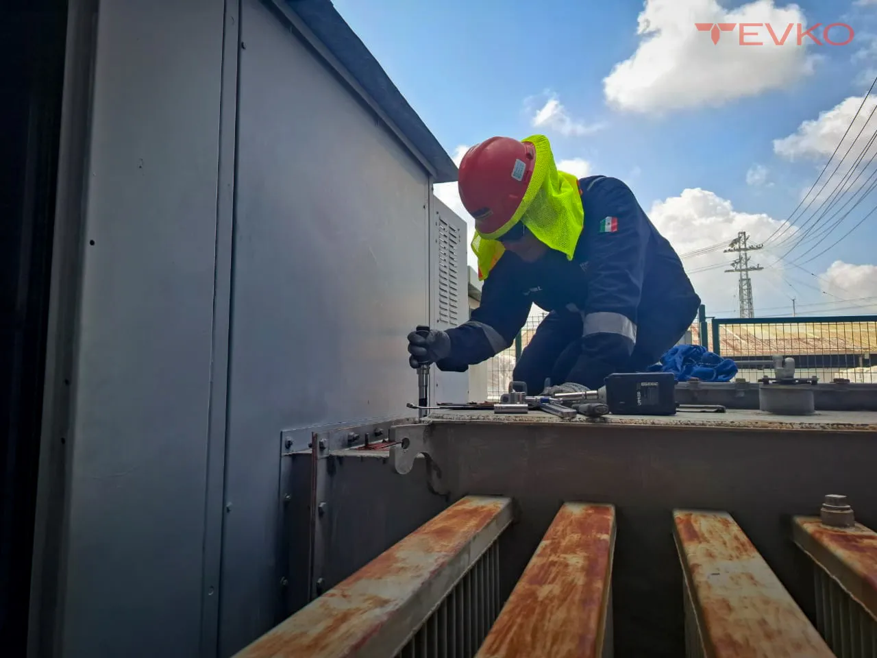
Ground (earthing) system measurement in images
Related tests and services
Talk to a transformer specialist
Tell us about your asset and we'll respond with a diagnosis and a tailored quote — not generic pricing.